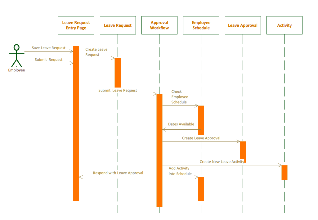

- #Loop in sequence diagram how to
- #Loop in sequence diagram full
- #Loop in sequence diagram software
- #Loop in sequence diagram code
Our goal is to be able to specify the structure of the system with USE, and the valid interactions with the textual MSC specification. The corresponding textual specification of the SD of this system described using MSC grammar is the following: The class diagram describes the objects and the operations they provide, while the UML sequence diagram shows the possible interactions. To illustrate this, the following figure shows a simple client-server system specified by means of a class and sequence diagrams. For this purpose, a grammar was defined using Xtext in order to parse the information in the MSC files and generate the corresponding SOIL scripts. To start with, we selected a subset of MSC to describe the most simple interactions and four combination operators: par, alt, opt, and loop. MSC is an international standard notation, UML SDs are based on MSC, and its rules are a subset of the latter. This is why we decided to use the ITU-T Message Sequence Chart (MSC) as the textual grammar for the specification of SD in USE. Given the textual character of USE, the natural manner to specify SDs is using a textual language, too. The tool that we developed is an extension of USE that enables this general specification.
#Loop in sequence diagram software
This way, software engineers could specify SDs in USE, and automatically have access to all behaviours that comply with these specifications.
#Loop in sequence diagram how to
This means that SDs are projections of executions and not general specifications of the possible interactions.įor this reason, we decided to investigate how to provide USE with capabilities for the general specification of SD, together with the automated generation of all the valid traces that comprise the semantics of such specifications in terms of SOIL scripts. In USE, they are automatically produced from the execution traces of scripts, allowing modelers to visualize the interactions which occurred between the objects in the system.

This feature enables the execution of scripts as a sequence of operations invoked by an external actor. However, USE does not allow to specify sequence diagrams that describe in general the valid execution traces of the system. USE provides a textual OCL-like action language called SOIL for specifying the behaviour of operations, together with an engine able to execute them. It is successfully used in lectures at different universities and also as a supporting tool for research.
#Loop in sequence diagram full
USE provides full OCL support and enables a full range of analysis capabilities. In our case, we are interested in one modeling tool, namely USE (UML-based Specification Environment), which is one of the most popular textual UML modeling tools. Furthermore, despite their apparent simplicity, SD can hide very complex behaviors and their specifications are in general difficult to understand. However, all this potential of SD is not fully exploited by most modeling tools, which only enable their representation.
#Loop in sequence diagram code
A few of those tools also provide analysis capabilities such as checking whether the trace of a program or model execution is valid, producing test cases, or even generating code from them. Most UML tools support the specification of SDs. A valid Sequence Diagram is an SD whose set of traces is allowed by the system specification and does not violate its constraints. Each SD defines a set of possible sequences of interactions between the objects of the system, called traces. The semantics of UML SDs are defined in terms of valid and invalid traces.

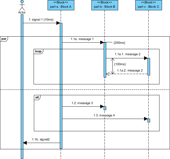
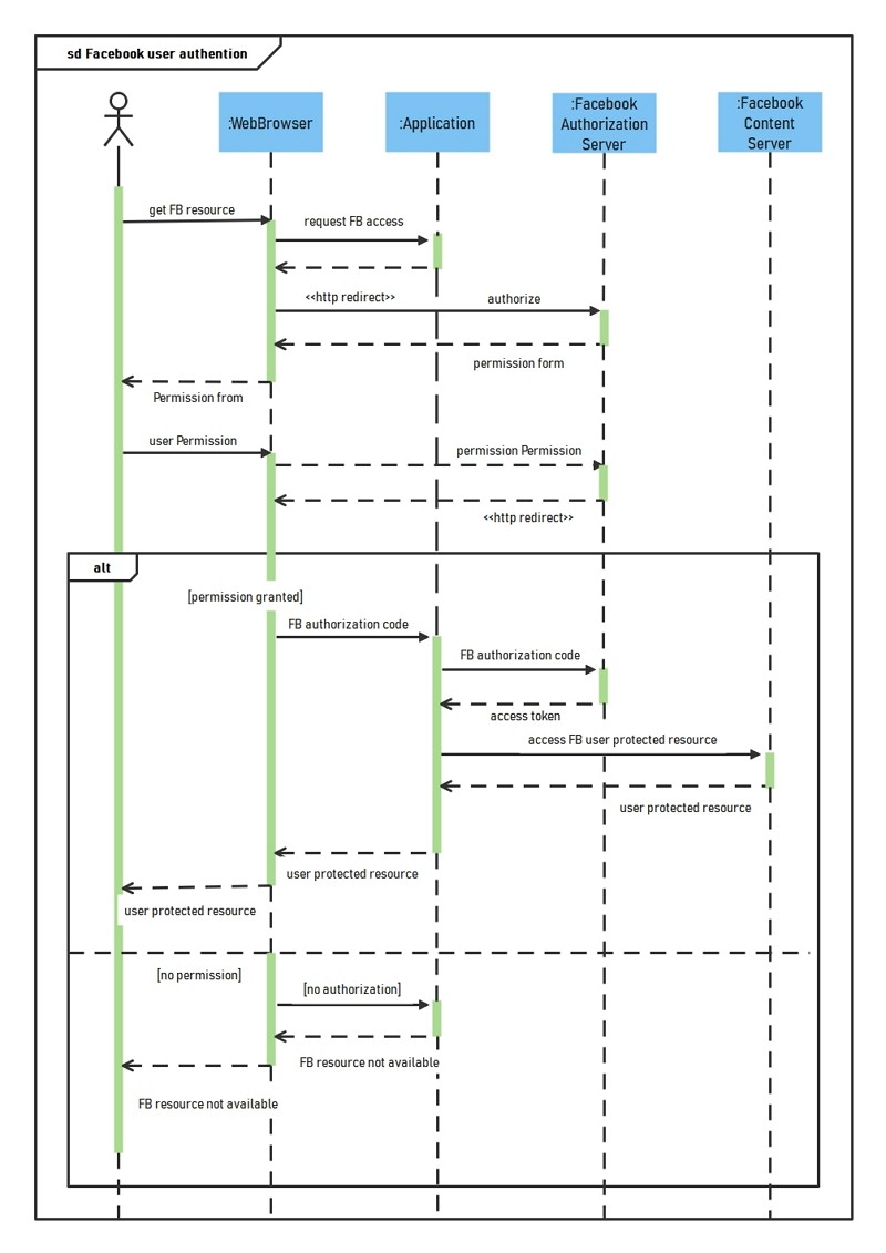
SDs support modularity mechanisms and combination operators, such as parallel, alternative, optional, or repeated action or event occurrences (par, alt, opt, loop) in the definition of the interactions. In UML, sequence diagrams (SD) describe a type of interaction that focuses on the partial order of message interchanges between objects.


 0 kommentar(er)
